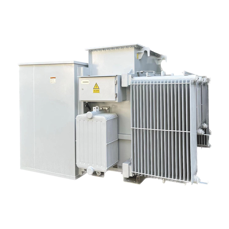
Power transformers are critical assets in electrical grids, responsible for voltage conversion and power transmission. Their reliable operation is paramount to grid stability. Overexcitation, a common abnormal condition in transformers, occurs when the magnetic flux density in the core exceeds the rated value, leading to increased core losses, overheating, and potential insulation degradation. Overexcitation protection (OEP) is thus essential to detect such conditions and initiate timely actions, preventing catastrophic failures. This article elaborates on the configuration principles, setting methodologies, and key considerations of overexcitation protection in
power transformers.
Overexcitation is primarily driven by an imbalance between the applied voltage (V) and system frequency (f), as magnetic flux (Φ) in the transformer core is proportional to V/f (Faraday’s law: Φ ∝ V/f). Key causes include:
Overvoltage Conditions: Sudden voltage surges due to load rejection, faulty voltage regulation, or capacitor bank switching can elevate V beyond the rated value, increasing V/f.
Underfrequency Events: Grid frequency drops (e.g., due to generator tripping or excessive load) reduce f, raising V/f even if V remains nominal.
Transformer Energization: During energization, transient overvoltages (e.g., inrush currents) may temporarily increase V/f.
Regulator Malfunctions: Automatic voltage regulators (AVRs) or tap-changers failing to adjust voltage correctly can cause sustained overvoltage.
The consequences of overexcitation are severe:
Increased Core Losses: Hysteresis and eddy current losses rise exponentially with flux density, causing core overheating.
Insulation Degradation: Sustained high temperatures accelerate insulation aging, reducing transformer lifespan.
Mechanical Stress: Excessive flux induces vibrations in core laminations, leading to structural damage over time.
Overexcitation protection systems are configured to monitor V/f ratios and trigger protective actions (e.g., alarms, tripping) based on predefined thresholds. The configuration involves selecting appropriate hardware, sensing points, and coordination with other protection schemes.
Modern OEP relies on microprocessor-based relays, which offer:
Accurate measurement of V/f ratios using voltage transformers (VTs) and frequency sensors.
Programmable time-delay characteristics to match transformer thermal withstand capabilities.
Communication interfaces for integration with SCADA systems, enabling remote monitoring.
Voltage and frequency signals are typically sourced from:
Primary Side: VTs connected to the high-voltage (HV) winding, providing direct measurement of applied voltage.
Secondary Side: For step-down transformers, VTs on the low-voltage (LV) side may be used, but HV-side sensing is preferred for faster response.
Frequency Measurement: Derived from voltage signals (via zero-crossing detection) or dedicated frequency transducers.
OEP is often configured with two-stage operation to balance sensitivity and selectivity:
Alarm Stage: Triggers an alarm when V/f exceeds a moderate threshold (e.g., 1.05–1.1 times rated V/f), alerting operators to adjust voltage/frequency.
Trip Stage: Initiates transformer tripping if V/f reaches a critical level (e.g., 1.2–1.3 times rated V/f) for a sustained period, preventing irreversible damage.
Coordination with other protections (e.g., overcurrent, differential protection) is critical to avoid false trips. For example, OEP time delays should be longer than transient disturbances (e.g., motor starting) but shorter than the transformer’s thermal endurance limit.
The setting of OEP parameters is based on the transformer’s V/f capability curve, provided by manufacturers, which defines the maximum allowable V/f ratio (overexcitation factor, OF) versus duration. Key parameters to set include:
The overexcitation factor is defined as:OF=Vrated/fratedVactual/factual
Alarm Threshold: Typically set at 1.05–1.1 pu (per unit) of the rated V/f ratio. This value is chosen to detect incipient overexcitation without nuisance alarms.
Trip Threshold: Determined by the transformer’s thermal limits. For example, a trip at 1.2 pu may be set with a time delay of 10–30 seconds, while 1.5 pu could trigger tripping in 1–5 seconds, aligning with the manufacturer’s curve.
Time delays are inverse-time to accommodate transient overexcitation (e.g., during energization) while acting on sustained conditions. The curve is derived from:
Manufacturer Data: Transformer-specific V/f endurance curves (e.g., 1.05 pu for 60 minutes, 1.2 pu for 2 minutes).
System Requirements: Coordination with grid recovery measures (e.g., allowing temporary overexcitation during frequency restoration).
For a transformer rated at 220 kV, 50 Hz:
Rated V/f ratio = 220,000 V / 50 Hz = 4,400 V/Hz.
Alarm setting: 1.05 × 4,400 = 4,620 V/Hz (delay = 60 s).
Trip setting 1: 1.2 × 4,400 = 5,280 V/Hz (delay = 20 s).
Trip setting 2: 1.5 × 4,400 = 6,600 V/Hz (delay = 2 s).
Accuracy of Sensing Devices: VTs and frequency sensors must be calibrated to ensure precise V/f measurement, as errors can lead to under/overprotection.
Transient Immunity: The protection should ignore short-duration V/f spikes (e.g., <10 cycles) caused by switching operations.
Generator-Transformer Units: In generator-transformer systems, OEP must coordinate with generator AVRs to avoid conflicting actions during voltage/frequency adjustments.
Renewable Integration: High penetration of renewables (e.g., solar, wind) may increase voltage/frequency fluctuations, requiring more adaptive OEP settings.
Overexcitation protection is a vital safeguard for power transformers, mitigating risks associated with excessive V/f ratios. Proper configuration—encompassing device selection, sensing points, and coordination—and accurate setting based on manufacturer curves and system requirements are critical to ensuring reliability. As grids evolve with smart technologies, future OEP systems may integrate real-time data analytics to enhance responsiveness and adaptability, further securing transformer operations in dynamic electrical networks.