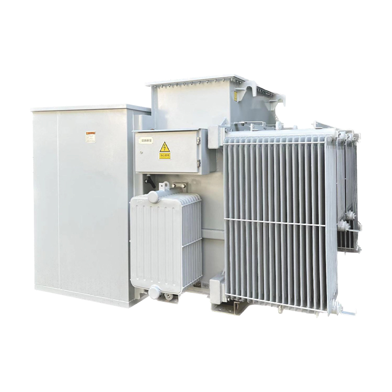
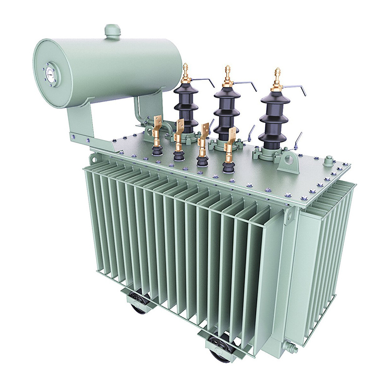
A power transformer is a static electrical device that transfers electrical energy from one circuit to another through electromagnetic induction, without changing the frequency. It mainly consists of a core, primary winding, and secondary winding. The core, made of high - permeability magnetic materials such as silicon steel sheets, provides a magnetic path for the magnetic flux. The primary winding is connected to the input power source, while the secondary winding is connected to the load circuit.
The operation of a power transformer is based on Faraday's law of electromagnetic induction, which states that when the magnetic flux linking a coil changes, an electromotive force (EMF) is induced in the coil. Mathematically, it is expressed as e=−NdtdΦ, where e is the induced EMF, N is the number of turns in the coil, and dtdΦ is the rate of change of magnetic flux.
When an alternating current flows through the primary winding, it generates an alternating magnetic flux (Φ) in the core. This magnetic flux links with both the primary and secondary windings. Since the magnetic flux is common to both windings and is constantly changing (due to the alternating nature of the current), an EMF is induced in the secondary winding according to Faraday's law.
The voltage transformation ratio of a transformer is determined by the ratio of the number of turns in the primary (N1) and secondary (N2) windings. The relationship between the primary voltage (V1) and secondary voltage (V2) is given by the equation V2V1=N2N1. If N2>N1, the transformer is a step - up transformer, increasing the voltage from the primary to the secondary side. Conversely, if N2<N1, it is a step - down transformer, reducing the voltage.
The current transformation in a transformer follows the principle of conservation of power. Neglecting losses, the power in the primary (P1=V1I1) is equal to the power in the secondary (P2=V2I2). From the voltage - turn ratio and the power - conservation equation, we can derive the current ratio I2I1=N1N2. So, the current in the windings is inversely proportional to the number of turns.
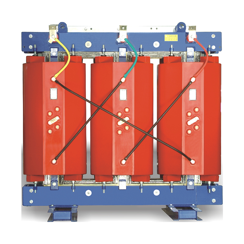
The magnetic circuit of a power transformer plays a crucial role in its operation. The core is designed to have a low reluctance path to minimize magnetic flux leakage. Silicon steel sheets are used for the core because of their high magnetic permeability and low hysteresis loss. Hysteresis loss occurs due to the cyclic magnetization and demagnetization of the core material and is proportional to the area of the hysteresis loop of the material.
Eddy - current losses also occur in the core. To reduce these losses, the core is laminated. Lamination involves stacking thin sheets of silicon steel with an insulating layer between them. This breaks up the eddy - current paths, reducing the magnitude of the induced eddy currents and thus minimizing the eddy - current losses.
To analyze the behavior of a power transformer under different operating conditions, an equivalent circuit model is used. The simplified equivalent circuit of a transformer referred to the primary side consists of a series combination of the primary winding resistance (R1), primary leakage reactance (Xl1), magnetizing reactance (Xm), and core loss resistance (Rc). The secondary winding parameters (R2 and Xl2) are referred to the primary side using the turns - ratio squared (k2=(N2N1)2).
This equivalent circuit helps in calculating various performance parameters such as voltage regulation, efficiency, and power transfer characteristics of the transformer under different load conditions.
When the transformer is operating under no - load conditions (i.e., the secondary winding is open - circuited), a small current, known as the no - load current (I0), flows through the primary winding. This current has two components: the magnetizing component (Im), which is responsible for creating the magnetic flux in the core, and the core - loss component (Ic), which supplies the power required to overcome the hysteresis and eddy - current losses in the core.
When a load is connected to the secondary winding, a current (I2) starts flowing through the load. According to the principle of electromagnetic induction, this current in the secondary winding modifies the magnetic flux in the core. To maintain the magnetic - flux balance, the primary current increases from the no - load value (I0) to a new value (I1) that satisfies the current - ratio relationship I2I1=N1N2. The presence of the load also causes voltage drops in the winding resistances and leakage reactances, affecting the terminal voltages on both the primary and secondary sides.
In conclusion, the working principle of
power transformers is a complex yet well - understood phenomenon based on electromagnetic induction, magnetic circuit theory, and electrical circuit analysis. Understanding these principles is essential for the design, operation, and maintenance of power transformers in modern electrical power systems.