The capacity of a power transformer (rated in kVA or MVA) must match the electrical load requirements of the system to ensure safe, efficient, and economical operation. Key principles include:
Matching Load Demand: The transformer’s rated capacity should slightly exceed the maximum expected load to avoid overload and premature aging.
Future Growth: Account for anticipated load increases over the transformer’s lifecycle (e.g., 5–10 years).
Efficiency Optimization: Transformers operate most efficiently at 30–60% of their rated capacity. Over-sizing leads to high no-load losses, while under-sizing risks overheating and reduced lifespan.
Accurate load calculation is critical for determining the required transformer capacity. Below are common methods:
Uses a demand factor (DF), defined as the ratio of maximum demand load to the sum of all connected loads.Demand Load (kVA)=Connected Load (kVA)×Demand Factor (DF)
List all connected loads (e.g., motors, lighting, appliances) and sum their rated capacities (Stotal).
Apply the demand factor (typically 0.3–0.8, depending on the industry; e.g., 0.6 for commercial buildings).
Include diversity factors if multiple loads do not operate simultaneously.
A commercial building has 100 kW of connected loads with a DF of 0.7.Demand Load=100kW×0.7=70kW(≈87.5kVA at PF=0.8)
Accounts for the probability that not all loads will operate at full capacity simultaneously.Diversity Factor (DF)=Total System Maximum DemandSum of Individual Maximum Demands
Calculate the maximum demand for each load or load group.
Sum these individual demands (Sindividual).
Divide by the diversity factor (typically >1; e.g., 1.2–2.0 for industrial systems) to get the total system demand.Total System Demand (kVA)=Diversity FactorSindividual
Estimates future loads using historical data or industry trends.Sfuture=Scurrent×(1+r)n
A current load of 500 kVA with 4% annual growth over 5 years:Sfuture=500×(1+0.04)5≈608kVA
Ensure the transformer can withstand short-circuit currents using the formula:Isc=Z%×Vbase/SratedVrated
Account for transient inrush currents (5–10× rated current) during energization, which can affect protective device settings.
Classify Loads: Categorize loads into constant (e.g., lighting) and variable (e.g., motors) types.
Calculate Total Connected Load: Sum all load ratings in kVA.
Apply Demand and Diversity Factors: Reduce the total load to reflect actual operating conditions.
Include Load Growth: Add a buffer for future expansion (e.g., 20–30%).
Select Standard Rating: Choose a transformer with a rated capacity ≥ calculated demand (e.g., 100 kVA, 250 kVA, 1 MVA).
Scenario: A factory has the following loads:
50 kW motors (PF = 0.8, DF = 0.7)
30 kW lighting (PF = 1.0, DF = 0.9)
Anticipated 5-year growth: 15%
70.75×1.15=81.36kVA
Choose a 100 kVA transformer (next standard rating above 81.36 kVA).
No-Load Losses (Pcore): Constant losses due to core magnetization; minimize by selecting high-efficiency transformers (e.g., non-crystalline alloy cores).
Load Losses (Pcu): Vary with load; proportional to I2R. Use the formula:Efficiency (%)=Load Power+Pcore+PcuLoad Power×100
Ensure voltage drop under full load is within acceptable limits (typically ±5% for distribution systems). Use:Voltage Regulation (%)=VratedVno-load−Vfull-load×100
Ambient Temperature: Derate capacity for high temperatures (e.g., 1% per °C above 40°C).
Altitude: Reduce capacity by 1% for every 100 m above 1000 m due to reduced air density.
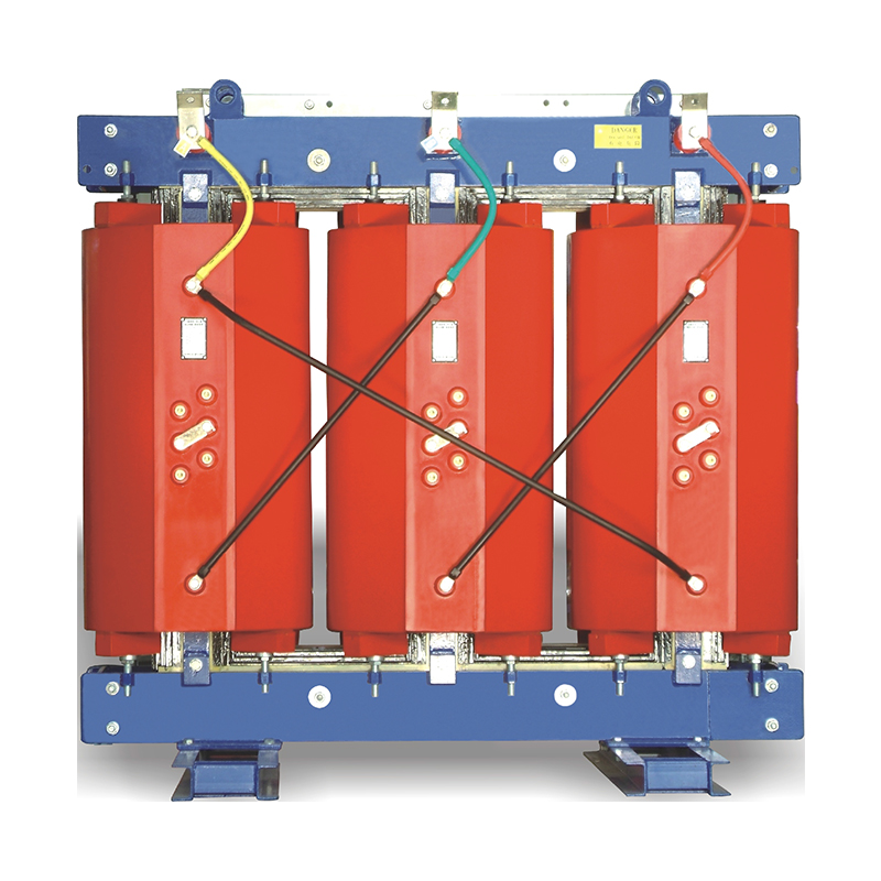
Cooling Method: Dry-type transformers have lower heat dissipation than oil-immersed types; adjust ratings accordingly.
IEEE Std C57.12.00: Specifies transformer ratings and performance criteria.
IEC 60076: Defines international standards for power transformers.
Local Electrical Codes: Adhere to national regulations (e.g., NEC in the U.S., BS 7671 in the UK) for safety and compliance.
Selecting the appropriate transformer capacity requires a systematic approach to load calculation, future growth planning, and technical optimization. By combining demand factor analysis, diversity considerations, and adherence to industry standards, engineers can ensure reliable, efficient, and cost-effective power distribution. Always prioritize safety, energy efficiency, and scalability to meet evolving operational needs.